


Introduction:
AC wave shapes, and DC magnitudes in sophisticated applications are important. Surprises that result in failure can be avoided by understanding real circuit behavior, rather than estimations or guess work. Evaluation of insulation and leakage currents are valuable as well. High voltage circuits (~above 10kV) are specialized, the components are often difficult and expensive to purchase or make. Understanding the function of the actual circuit allows the right components to be bought, reducing cost and assuring reliability. Most often, in my experience, the association of a low voltage transistor input pulse causing a high voltage output pulse is essential.Research:
![]()
Research:
High voltage probe for O-scope, 1 of 2, ( DEVELOPMENT ).
High voltage probe for O-scope, 2 of 2, ( FABRICATION ).
Maro denicolais site
![]()
 Systems Studied:
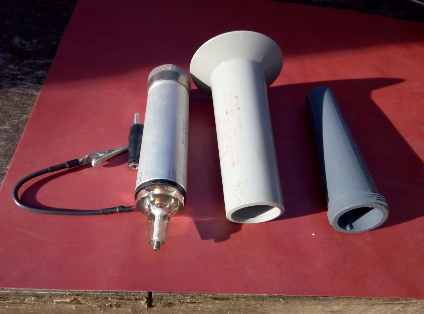
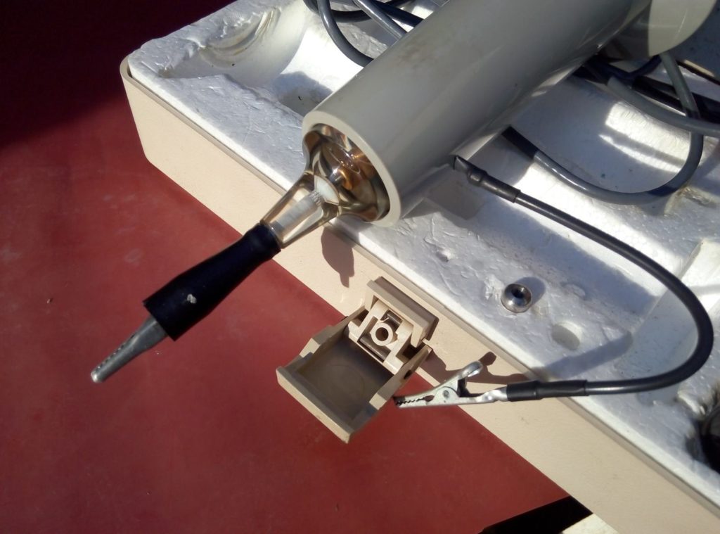
Dissection of known systems, the Tektronix high voltage P6013, P6015A probes, and common low-bandwidth probes.
The Tektronics P6013 probe. Capable of 12kV then derated as frequency rises. This probe is air insulated, which is a significant disadvantage.
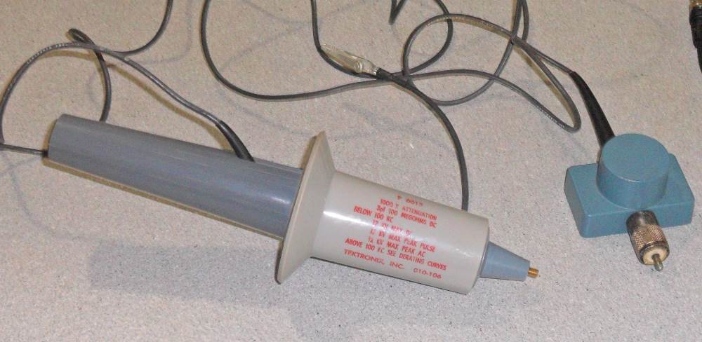
The Tektronics P6011 probe. A high bandwidth probe for use up to 40kV. Derating does become necessary above certain frequencies.

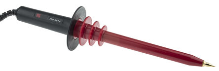
Generic low frequency high resistance probe for a common Volt meter. Low frequency and no compensation, not capable of more than line frequency or a little more.
![]()
Texts:
Important Excerpts from “High Voltage Engineering Fundamentals” E. Kuffel, W.S. Zaengl. Pergamon Press.
( ISBN: 0-08-024213-8 ) This book is essential to understanding previous successful devices developed by others, and the physics present.
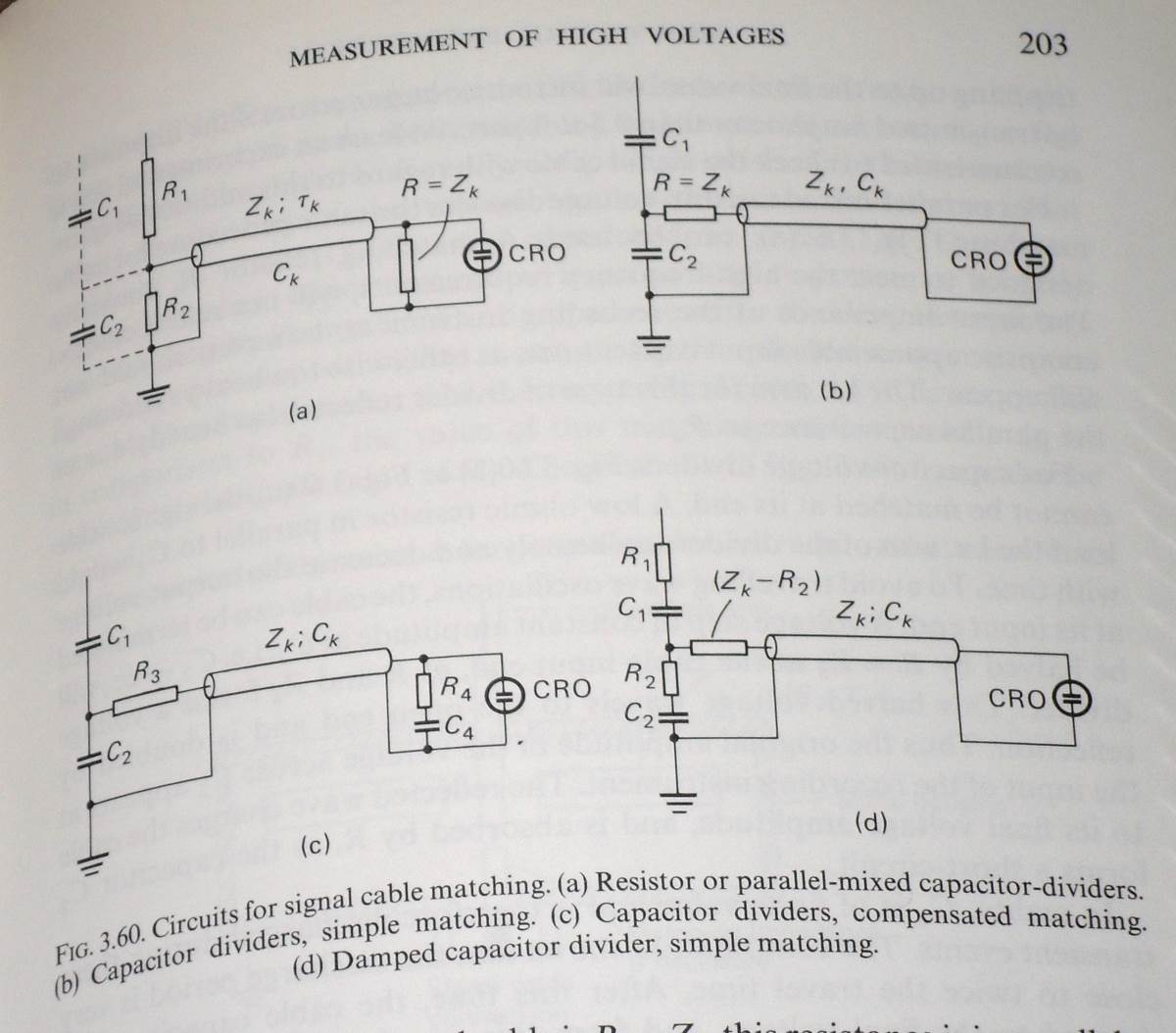
Toriod with Resistors. Non-ideal features shown as well.
Seen at the left a high voltage probe with descriptions of the non-ideal features all probes are subject to. Stray capacitance and inductance must be charged and discharged as the waveform changes, which makes the reported waveform bogus. Situation worsens as frequency and resistance increase.
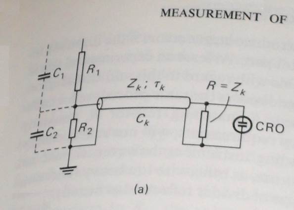
 Seen in the picture to the left, a vertical resistor, grounded at the bottom and
voltage applied to the top. The dashed lines indicate the e-field. In the right hand example the toroid influences the field shape more and more as we move from the ground upward. Looking at the schematic, left, we see that as the voltage drop increases linearly upward (the Y-axis in this case), as does the field intensity. Note that field intensity and field shape can be quite different from each other.
Marco Denicolai’s work:
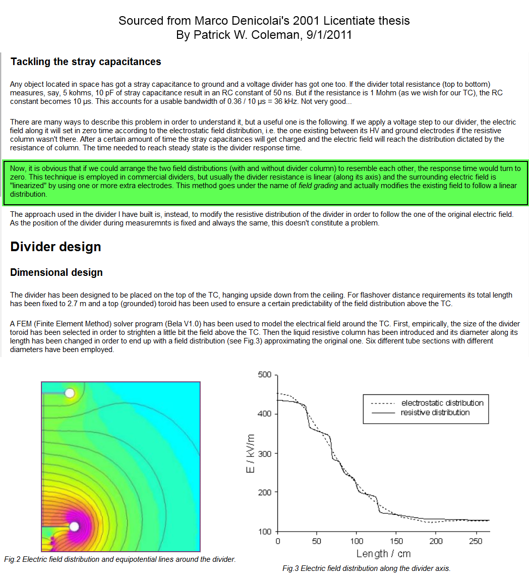
Marco Denicolai’s Licentiate Thesis
Note above what I have highlighted in green. This statement is extremely important in understanding the solution both Denicolai and I chose.
![]()
Experimental Builds:
Analysis:
abc
abc
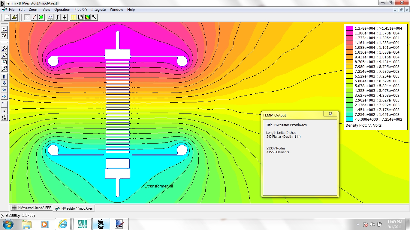
In the above FEA graphic, we can see the high voltage at the top of the resistor (magenta), and the lowest voltage at the bottom (cyan). And with uniform resistance from top to bottom we Kirchhoff and Ohm tell us the voltage drop and field must be uniform. And the Equipotential lines with linear-zed by the capacitor plates, we have a high frequency capable system.
![]()
Lessons Learned:
spectrum of operation.
![]()
Fabrication:
pics to follow
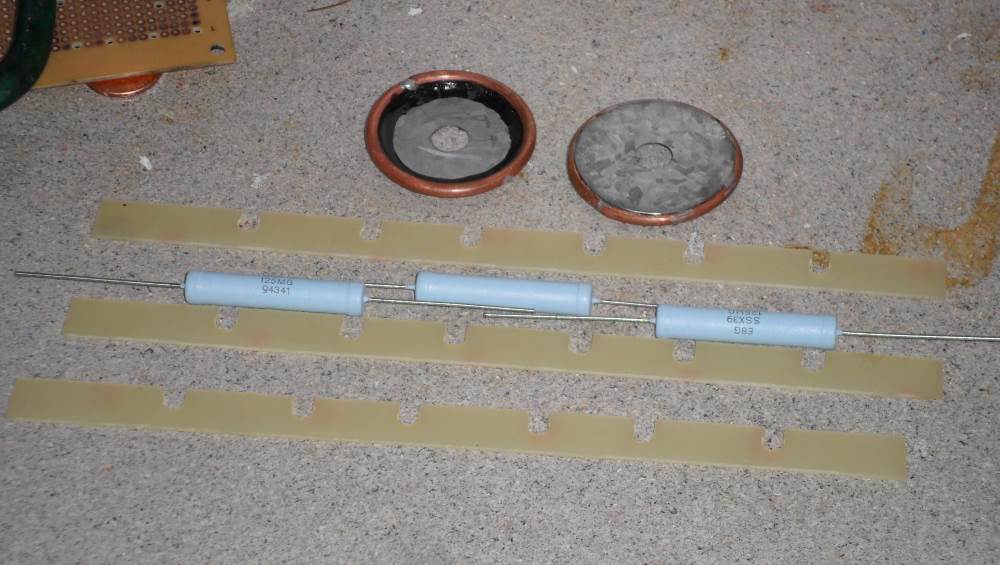
High Voltage resistors in series.
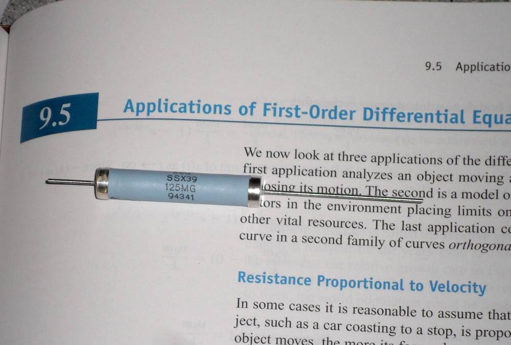
High Voltage resistor, removing the silicone encapsulate.
![]()